Video courtesy of BrainShaw33
The damage must have occurred after a particularly heavy meeting with the ground recovering from inverted, although I must say I had not noticed it at the time as I called it a day with that unscheduled landing as I was aware that the batteries were low. The damage that had gone unnoticed initially was to the two posts that come vertically out of the landing gear to mount it in the main frame. These had both split near their base but neither had come broken clean off. It was only the next time that I tried to fly the mCPx that it became apparent that something was amiss as the helicopter was very unstable and pretty quickly came down. Close inspection then revealed that one of the posts had broken off while the other was near to doing so. Not of itself a problem, just pick up a new set of landing skids and you are away again.

When you realise that the post has broken off right at the base with the post itself still wedged in the main frame things are not so straightforwards; at least not when you discover that the little plastic post can not be coaxed out by pulling or levering it and is even resistant to any attempts to drill it out.

At that point the only remaining option is to get a new main frame as well as a new set of landing skids.
So a few days later the items have arrived - together with one of the new tail rotor blades for the V2, which I thought I would get to try while I was ordering. These have a wider blade with a greater pitch angle on it to provide better tail holding capabilities, or so they claim.
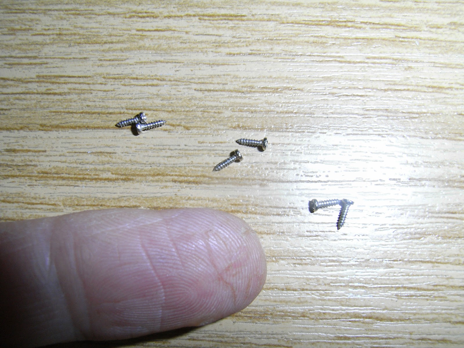
So with all parts at the ready I proceeded to set about the job of changing the main frame. You will need good light and if your eyesight is not 100% then probably a magnifying glass as the parts are tiny. Neither is it a job for anyone who is all thumbs!
The first step is to remove the tail boom and disconnect the tail motor plug from the main board. The boom comes free without too much trouble if you give it a sharp pull. I recommend that you first unplug the tail motor because giving a sharp pull on the tail boom can lead to it jolting away quite rapidly leading to you yanking the cable from the tail motor to the main board. The result may be damage to the wiring or the plug.

That done and the canopy removed I moved onto removing the main shaft. If you take the main gear off and disconnect the 3 pushrods from the swashplate the main shaft will then lift out complete. It is also necessary to remove the top and bottom bearings from their housing in the main frame. It is wise to note which way round they sit when doing so. I would describe them as having a closed side (has larger flanges) and an open side (whereby you can see more of the bearings). In each case it is the 'closed' side which faces out when located in the main frame.

After that the servos can be removed. I left all of these plugged into the main board. This seems to be the simplest option but alternatively you could unplug them, having first clearly marked which one goes where. I also left the servo pushrods in their respective servos, although these can quite easily drop out.

Having removed the three servos I next removed the main board. This is again held in place with 2 screws, each with their own washer so that the screws can be bedded down firmly without damaging the more fragile material of the main board. These two screws are also longer than those used to locate the servos.

Next the main motor can be unscrewed. Again two hex screws hold it in place (Note these are short, stubby screws). Then the motor can be slotted out from its quite tight housing.

That done you are left with the old main frame separated from its fixtures.

All the parts attached to the main frame are held in place by a sum total of 5 pairs of screws.

One new main frame waiting to be made up into a 3D flying machine.
Putting it all back together again in the main frame is basically a reverse of the above process of taking it apart.
Then in goes the motor, followed by the two lateral cyclic servos. Just make sure that you get the servos on the correct side or your swash plate movements will be reversed.
When it comes to replacing the elevator servo at the rear there is a definite trick to it. It is necessary to ensure that the servo pushrod is attached to the servo BEFORE you put the servo back. There is no way to do it afterwards. Furthermore the servo pushrod has to be the right way around. The pushrod should be on the inside with the short hooked end on the outside.


Correct placement with the servo pushrod arm central and the hook to the outside.
Incorrect placement with the servo pushrod arm on the outside.
Having made sure that the servo pushrod is correctly attached to the servo the next point is to ensure that when putting the servo back in place that you lead with the servo pushrod, slotting it through the oblong plastic frame opening on the top between the upper main bearing, to the front, and the tail boom mount to the rear.

With that done the fitting of the main frame is all but complete.

All that remains now is to put the complete main shaft back on, re-attach the servo pushrods to their respective ball ends and replace the tail boom. When replacing the tail boom wrap the motor wire back along the top of the tail boom so that when the boom is pushed back into the main frame the wire slots into the grove for it above the tail boom hole.
Next ensure that the swash plate is level. The pushrods may have changed length if the ball links have become screwed on more or less in the process. Further, there is no guarantee that the two mainframes will be identical and if the servo locations are slightly different the servo pushrod lengths will need to be changed. It is then a matter of attaching a LiPo to provide power in order to centre all the servos. The length of the various servo pushrods, respectively, can then be changed as required by screwing the ball links on or off a turn or so until the swash plate is level in all orientations.

If unable to get the swash completely levelled by eye by adjusting the pushrods, as these may not make fine enough changes on such a small helicopter, then it can be fine tuned using the sub-trim of the transmitter (if using a radio like the Spektrum DX6 or 7) or if using a lower specification transmitter that does not have this you will have to adjust it with the trims.
All that then remains is to check that all the controls are operating the swash in the correct directions and take a test flight to making any final adjustments to the trims.
So what was the cost of this?
BLH3505 Main Frame w/hardware £4.99
BLH3504 Landing Skid & Battery Mount £4.50
Total cost £9.49
I also fitted a new style tail rotor as mentioned before, BLH3603 £1.50
Now how does that compare with the cost of accident repairs on say a 450 size helicopter? Probably 5 to 10 times cheaper; plus there are alot less parts to break, it is very much more resilient to crashes and so much more straight forward to repair (if you can handle the tiny size of everything!). The only tool that I needed to use throughout was the provided jewellers screwdriver.
It is no wonder that these little micro-size 3D RC helicopters are becoming so popular!
So is the Blade mCPx the only real choice in this niche of the RC helicopter market!
Absolutely not. Here are 3 other major contenders from Walkera worthy of more than just serious consideration:
- The Walkera Genius CP
- The Walkera Mini CP: this one you don't even need to pick up when it crashes!!!
- The Walkera V120D02S
Keep flying, and ENJOY!!!
Nice sharing reagriding the replacement of rc plane parts
ReplyDeleteIt is really a good post.Flying remote control helicopters has become a wonderful hobby that is open to all. Find More
ReplyDeleteAwesome blog post. Thanks for sharing this post. I like very much to learn remote control helicopters information in this post. RC Helicopter India
ReplyDelete